
$74.90
Free delivery · 7–14 days
Bicycle Speaker with Bluetooth, FM Radio & LED Light




Build a working digital FM radio from loose parts, then watch your own station glow in red on a clear acrylic case. The TEA5767 tuner and STC 51 microcontroller sit on a board you solder yourself, so every part stays visible. Finished, it is a desk piece you made.
Read the full descriptionBuild a working digital FM radio from loose parts, then watch your own station glow in red on a clear acrylic case. The TEA5767 tuner and STC 51 microcontroller sit on a board you solder yourself, so every part stays visible. Finished, it is a desk piece you made.
Build your own digital FM radio with a see-through acrylic case and LED frequency display
Stop staring at finished gadgets you didn't make. Solder the loose parts yourself, then watch your own FM station glow in red on a clear acrylic case.

The TEA5767 digital FM tuner picks up stations, and the STC 51 microcontroller handles the controls on the board you solder. Nothing is hidden inside a sealed shell. If you want more radio gear to pair with it, check the radio and headset range.

The four-digit red LED shows the exact frequency you are tuned to, such as 102.8. You always know which station is playing, and the display is bright enough to read across the room.

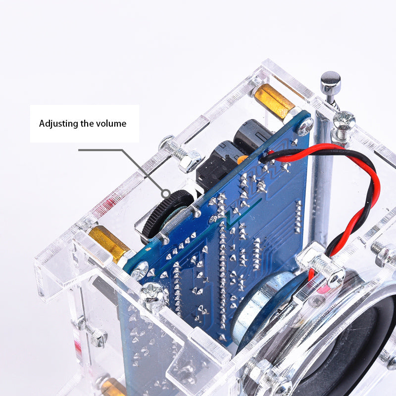
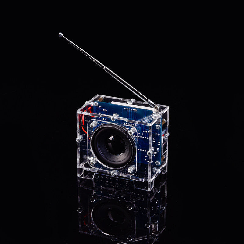
The acrylic panels screw onto standoffs around the board, so the PCB, chips and speaker stay in view. You can point at every part you soldered while the radio runs.
Lay out the PCB, acrylic panels, speaker, telescopic antenna, power cable and screws. Check that every part in the box is there before you start.
Populate the PCB in stages, starting with the low-profile parts. Watch the polarity on the electrolytic capacitors and match the marked negative leg to the printed mark on the board.
Look at every joint under good light and check for bridges between pads. Fix any problem now, because a short can damage the chips once the radio has power.
Attach the panels with the screws and standoffs so the board sits flat and the display lines up with the front opening.
Connect the DC cable, extend the chrome antenna, and turn the volume knob up slowly. Tune to a station and the red display shows its frequency.
Blue board with the TEA5767 tuner and STC 51 microcontroller, ready to solder
Clear panels that form the see-through case
Built-in speaker wired to the volume potentiometer
Extends for FM reception
Powers the finished radio from a 5V supply
Holds the board and panels together

Most beginner projects end up in a drawer, half wired and never powered. Finished radios are easy to buy and teach nothing. You want a project that ends with something working on your desk.
The TEA5767 digital tuner finds the stations and the STC 51 microcontroller runs the controls. You populate the blue PCB yourself, so every chip you solder is a part you can point to when the radio plays.

Power it up, extend the chrome antenna, and the red display shows the frequency you are tuned to. The case stays clear, so the circuit keeps working in plain sight after the build is done.
| This kit | Finished FM radio | Breadboard FM module | |
|---|---|---|---|
| You solder it yourself | — | ||
| Ready to play out of the box | — | — | |
| Circuit visible in a clear case | — | — | |
| Case and speaker included | — | ||
| Teaches microcontroller basics | — |
Yes. The PCB ships loose, so you solder each component yourself. You will need a soldering iron, solder and a clean, well lit workspace. The build is manageable for a first-timer who works slowly and checks each joint before moving on.
It does in most rooms with the antenna fully extended. Reception drops indoors, especially in basements or inside metal cabinets. Set the radio near a window and the stations come in cleaner.
Yes, if you are patient with small parts. The payoff is a radio that tunes real stations, which is worth more than a finished one that teaches nothing. Compared with buying a ready radio, you get the build, the circuit you can point to, and a working project for the cost of a single gadget.
A breadboard module needs its own wiring, a case and a speaker before it makes sound. This kit gives you a loose PCB, acrylic panels, speaker, antenna and power cable in one box, so the finished radio looks like a product rather than a tangle of jumper wires.
The radio runs on 5V DC through the included power cable. Connect it only after you have checked every solder joint for bridges.


 DIY TEA5767 Digital FM Radio Kit with Red LED Display